This site contains a lot of free info but if you have any questions simply email or telephone me for some personal help.
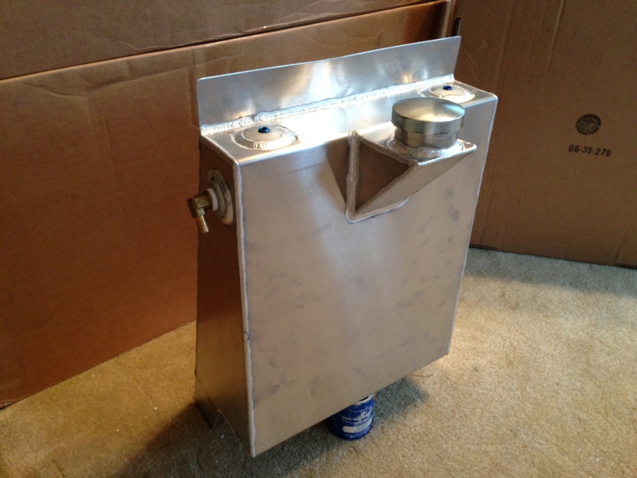
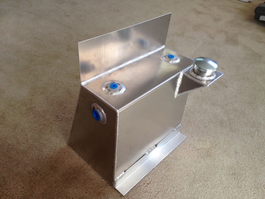
It is here and available NOW, the coolest RV-6-7-9 tank ever made.
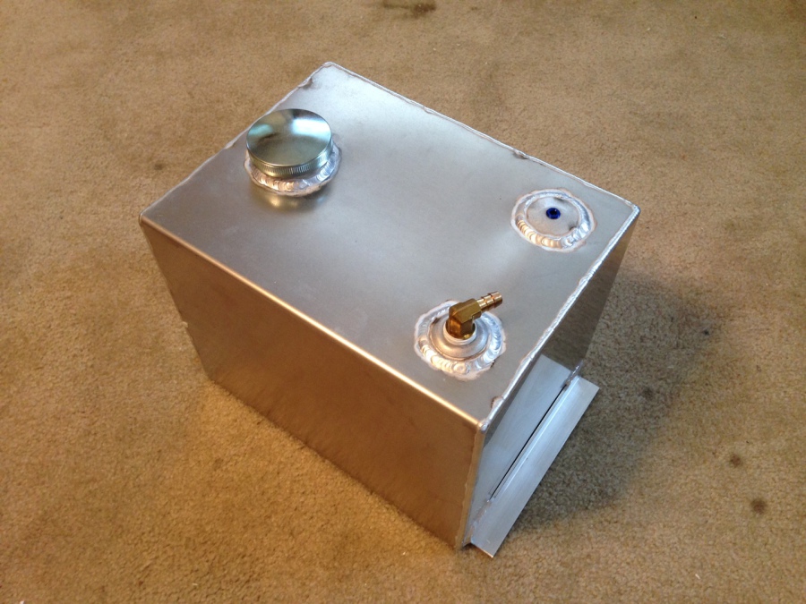
A custom flush fit tank for RV airplanes. This tank will not use ANY of your baggage compartment space and unless you look close you will not even notice the tank in the airplane. Ultra simple installation. Holds 4.25 gallons of smoke oil. Leaves all other tanks in the dust. Do not put an ugly tank in your airplane, this one is as beautiful as it is practical.
SMOKE OIL
5 Gallon container $65.
55 Gallon barrel $475.
Very low cost shipping on barrels. I will need your address by email to compute shipping cost.
____________________
Installation Instructions
For the Slider Canopy RV-6 RV-7 RV-9 with the “hidden” tank
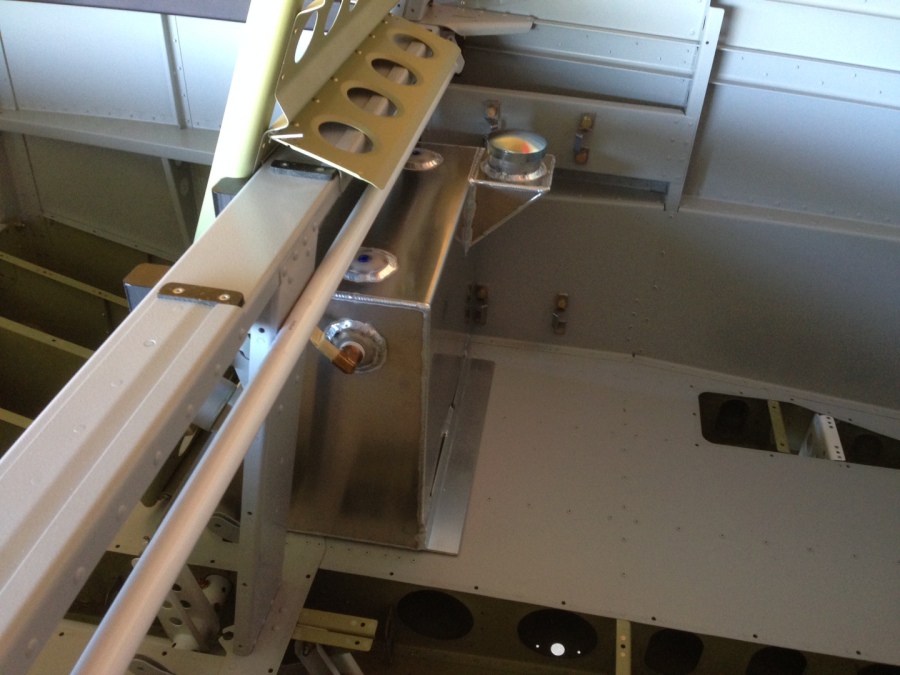
The upper flange on the tank goes IN FRONT of the crossbar.
For the Tip-Up Canopy RV-6 RV-7 RV-9 with the “hidden” tank
The upper flange on the tank goes INSIDE the crossbar instead of on the front of it. The mounting bolts will require a short spacer (provided) and a separate page is provided with an illustration of this.
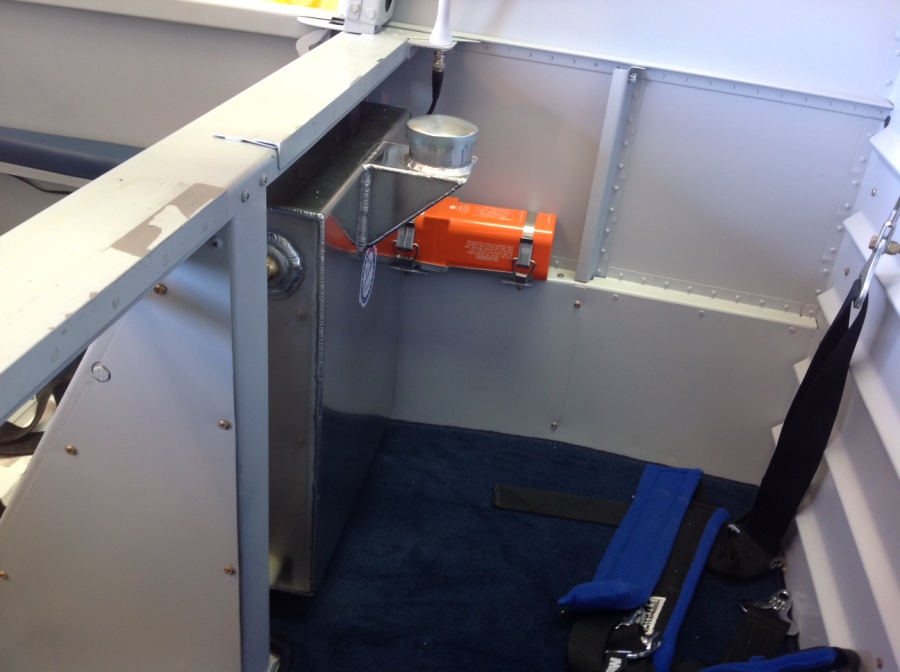
For either style canopy on the RV-6 -7 -9 you will need to remove the copilot seat and insert the tank slightly top down and moving front to rear. Push the tank all the way up as far as it will go allowing the short legs to rest on the floor. The legs will have to be trimmed slightly to fit the floor contour of your particular airplane. Just trim off a little at a time until you get a good fit to the floor. (Trimming is necessary because this tank fits more than one model RV and all floors are not the same)
Drill 3 or 4 holes thru the top tank bracket and the seat crossbar it is resting on and bolt it in place. Mark the location for the seat belt bolts to penetrate those short legs and drill holes there. Longer seat belt bolts are provided and several large area washers to use for spacers. Some of you will need a lot of spacers and some will only need a few spacers because all seat belt anchor brackets are not spaced exactly the same. Make sure the legs are firmly on the floor.
If you do not want to use the seat belt attach bolts to anchor your tank legs, there is another option. This option also makes the tank more easily removable. You can make a attach point for those legs on the tank by pop riveting a short piece of angle aluminum to your floor, then attaching the tank to those brackets. The material is provided for this optional attachment bracket, also a photo of the installation.
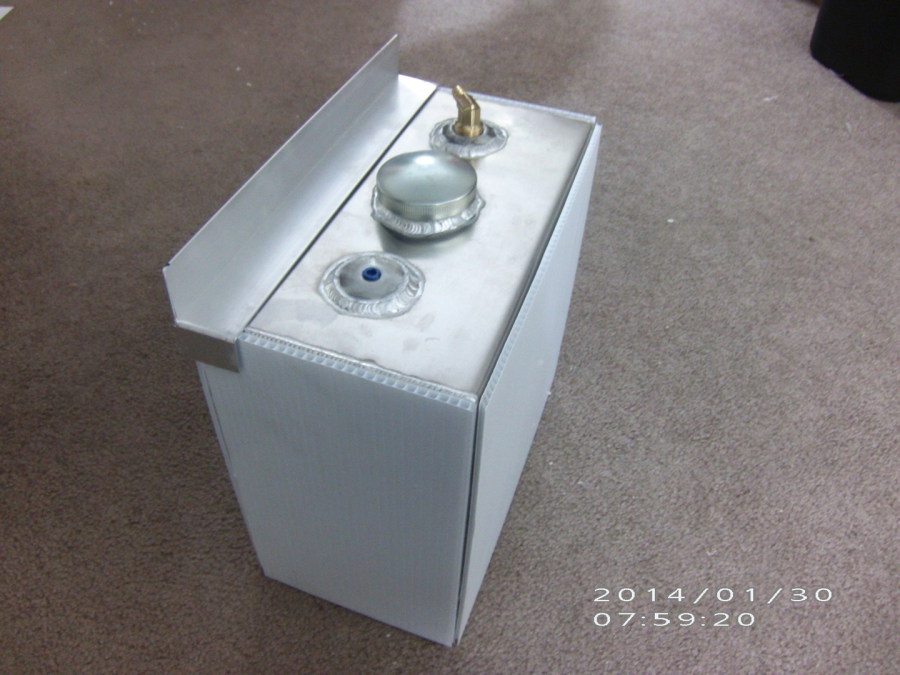
RV-8 Forward Deep Well Tank Install Instructions
The tank must be protected from metal to metal contact to avoid possibly rubbing a hole in the tank. That is the reason for the hard plastic covers on the tank.
Included with the tank is a foam pad ½ inch thick. This goes on the bottom of the well and the tank sits on it.
Now the tank can be placed into the well with the outlet fitting toward either the front or rear of the airplane.
Next place the hold down bar on top of the tank and bolt it in place using the existing screws or install new screws that are provided. Riv-nuts or nut plates can be used if you want the tank to be quickly removable. See the photo for hold down bracket placement.
The brass fitting has not been tightened because you will need to turn it to whatever position suits your hose routing plan.
The other tank outlet is a vent that will not be used unless you have full inverted systems in your airplane and plan on doing inverted flight.
In that case you will need to install the vent valve into the vent fitting in the tank and exchange the filler cap for a non-vented cap.
For most of us without full inverted fuel and oil systems the system is good as shipped for all positive “G” maneuvers and the vent valve is not needed. The inverted vent valve is an option and not included with the standard kit because most of us do not need it.
_______________________________________________
For the 3 or 4 or 5 or 8 gallon universal tank
Locate a good place to mount the tank and the oil pump. In most planes this is in the baggage area.
Mount the tank to the floor using the 4 screws and nuts provided.
If there is no access to the bottom side of your floor then riv-nuts or nut-zerks can be used and no rear access is needed. This will also make the tank easily removable.
Two different length screws are provided so do not be surprised when you have a few screws left over.
Pump Mounting
If you purchased the optional kit to mount the pump onto the tank just ignore this paragraph and there is a separate page of directions on how to mount the pump onto the tank.
One obvious option is to use the screws and nuts provided and bolt it to any surface. Nut-plates, Riv-nuts, or nut-zerks can be used to make the pump quick removable. Both screws and Riv-nuts are provided.
Another option is to remove the big square mounting bracket by removing the 2 screws that hold it to the pump. Now you can make a custom bracket and attach it to the pump with those 2 screws.
Another option is to remove the big square mounting plate and use hose clamps that go completely around the pump.
The pump can be mounted in any position, up, down, or sideways.
The pump should not be put on the engine side of the firewall because the heat may harm the plastic pump head, this has not been tested but plastic in the engine compartment is usually not a good idea.
Pump to tank connection
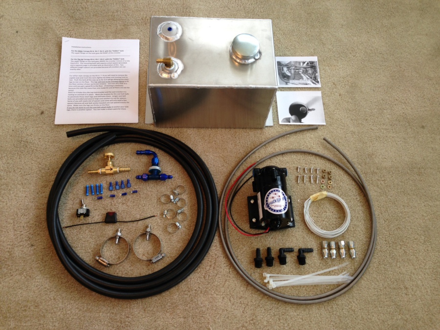
Using the black, rubber hose connect the tank to the input side of the pump, hose clamps are provided for all connections. DO NOT USE any metal fittings in the pump input or output sides. There is a chance you will crack the pump head before you get them tight enough not to leak. Normal metal AN fittings have been successfully used before but it is a little bit risky and you may ruin the pump. Plastic fittings in straight and 90 degree are supplied. In many years of using these plastic fittings, they have not given any trouble.
Run the rubber hose from the output side of the pump forward to the firewall. Place the adjustable needle valve anywhere in this line. It does not necessarily need to be in arms reach, in my plane it is not. This valve will adjust the oil flow so you make good smoke but do not waste oil. It only needs to be opened a small amount, usually about three quarters to 1 full turn UNLESS you have a big radial engine, then start with 2 full turns open or more. See the last page of these instructions for initial adjustment procedure before first flight. If you follow the instructions on the last page, you will have good smoke the very first time you try it out.
Install the “T” bulkhead fitting in any convenient place on the firewall. A step-drill (unibit) works well for making this hole in the firewall.
Install the AN-6 hose end on the firewall end of the rubber hose (it just pushes into the hose end) and connect the hose to the bulkhead fitting. This fitting is available in straight, 45 degree, and 90 degree styles. The 90 degree is by far the most popular so it is sent with the kit.
Oil Injector Mounting
On your exhaust pipe find a good location for mounting the oil injectors. Make sure the injector and attached hose will clear your cowling. The ideal location is on the front cylinder but it is not mandatory to go there. The rear cylinders also work about 95 percent as good, SEE THE PHOTO. The idea is to make the oil pass thru as much of the exhaust pipe as possible . CAUTION: If you have 2 exhaust pipes like most airplanes, make sure that your smoke will come out of BOTH of them. Mount the injector BELOW any EGT probes.
Drill a quarter inch hole in the exhaust pipe to mount the injector.
Tighten the two halves of the injector to each other but it will not tighten onto the hose clamp, this is normal.
Put the tip of the injector in the hole and tighten the hose clamp to hold it. There are 2 flat sides on the injector and that is where the hose clamp should touch it when you tighten the clamp. The flat sides will be parallel to the exhaust pipe. It aligns the spray pattern properly this way. See the photo.
Do this for both cylinders. If you cannot route the stainless steel hose to the front cylinders without it touching and rubbing against any other exhaust pipe then choose another place for the injectors, maybe the rear cylinders. The object is to make the oil flow thru as much exhaust pipe as possible for a cleaner burn. Make sure the hose fittings will clear your cowling. This hose does not make sharp bends.
Radial Engines
The 2 oil injectors can be either on the collector ring near the short, final exhaust tailpipe or on the tailpipe itself but try and keep the injectors roughly a foot from the end of the tailpipe.
Stainless steel hoses.
See the direction sheet and the YouTube video “Aeroquip 666 Hose Ends” for the procedure of putting the ends on the hose. No special tools are required but be careful not to stick your finger with that stainless steel braid, it will make you bleed. Most of the time all you will need are the straight fittings that are provided. If you need 45 or 90 degree fittings just let me know and I can exchange fittings with you for $10. more per fitting. The angled fittings do cost me more.
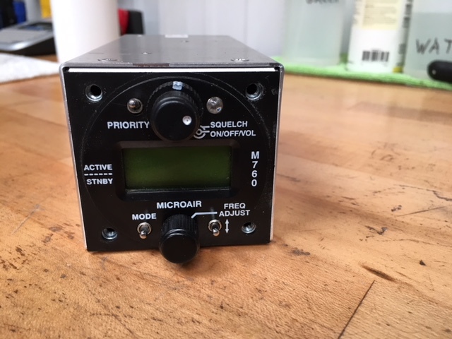
On/off switch.
Find a place to mount the switch in your instrument panel where it will be easy to identify by feel only, without having to look for it. This is important during formation flying. Mount the switch. A step-drill (unibit) works good for drilling this hole. You will need to test the switch with an ohm meter to see which switch position is on and off so you can put it in the panel oriented correctly.
Find a 12 volt source of power and attach one end of the fuse holder to it. From the other end of the fuse holder extend this wire to the switch and connect it to either terminal, push on connectors are supplied for the switch and also for splicing and extending the wire.
From the other connector on the switch run a wire back to the Red wire on the pump. The black wire on the pump can be connected to any convenient place on the metal airframe for a ground. Extra electrical terminals are provided for the remote possibility that you may mess up one of them.
You now have a working smoke system.
Put some oil in the tank, put some clean buckets under your exhaust pipes, turn it on and check for leaks. The oil can be re-used.
Adjusting your smoke oil flow rate.
When you ground test it there is usually a spot of oil on the ground, due to lack of airspeed this is normal if it is not a huge puddle. If you do a ground test, be careful, tail draggers can nose over and ruin your whole day.
Initial Adjustment, on the ground.
Put a clean bucket under your exhaust pipes to catch the oil, this way it can be reused and not wasted. As a general rule start with the valve open about ¾ of a turn. Turn on the pump for 1 minute and see how much oil you get, it should be approximately ½ gallon per minute. Open or close the needle valve until you get this amount of oil. Try not to run down your battery while you do this adjustment. This should give you good smoke the very first time you try it in the air. You may need to fine tune it a little more but not much. When you are happy with your smoke the valve does not need to be touched again.
Pilots flying big radial engines will have the valve open a lot more.
During the installation, if you have any questions do not hesitate to telephone or email, I am always available.
If you have any suggestions on how the system could be improved please let me know.
Have Fun
http://www.smoke-system-helper.com
419 360-7414 Any Time